
Culvert is an open/close drain structure that allows water to flow below a road. It’s like a tunnel carrying a stream of water flow.
A Ring/Pipe Culvert
Procedure for construction of a common Ring/Pipe Culvert (road
junction culvert) includes;
I. Marking Of Alignment: -

The surveyor marked out the
alignment for the trench to be dug.
II. Digging/Excavation:

The surveyor marked out the dept
of the culvert to be excavated with an excavating machine.
For a 1m pipe culvert, the
mathematical process of obtaining the required dept is to sum together the
total width of the pipe + base + blinding.
For dept:
A pipe of width 1000 mm, base of 150 mm and
blinding of 50 mm(though optional)..
Hence 1000mm + 150mm + 50mm = 1200mm
(1.2 m)
So an excavation of 1200mm (1.2m)
is required from the to level of the natural ground (sub grade level) surface.
For width:
A minimum of (2.5 x width) m is
advisable.
For a 1m pipe drainage,
Since the drainage internal width
is 1m, using
1.5 x width =
2.5 x 1m = 2.5m
2.5m width excavation minimum is
acceptable to create space for construction work area.
III. The next step after excavation of drainage
is the CONCRETE BLINDING and foundation base preparation.


Blinding (though
optional) is done on the surface area in order to correct any
irregularities in level of the bed of the excavated surface, and to provide a
smooth, level and regular surface to receive the concrete base. It’s usually ±50
mm depending on the rate of regularity of the surface area. Concrete grading
C15 is acceptable.
(See concrete grading and mix
ratio). A concrete base of ±150 mm is to be laid or cast on the blinded floor,
concrete grade C15 of ratio 1:2:4 is allowed (See concrete grading and mix
ratio).
A guiding panel is placed into
position to guild in the laying of the concrete base in order to achieve a
uniformly alignment base edge, thickness and width, also to manage concrete
material while pouring. The base is cast with the U shape reinforcement bottom
in between the concrete base achieving concrete cover below and above.
IV. After setting, curing and drying of the
concrete base, next is to arrange the pre-cast pipe Culvert/Rings into the
align position.


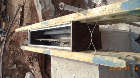
V. After arranging the pre-cast pipe
Culvert/Rings into the align position, arranging the form work panel and then casting
of concrete.
Taking the pipe/ring dimension to
be 1000 mm (1.0m), the thickness of the concrete from the form work panel to
the pre-cast ring/pipe is 200mm more or less on both sides depending on the
design.
Hence the total width thickness of
the drain would be;
i.e. 1000mm + 200mm + 200 mm =
1400mm (1.4m)
The total height of the drain
would be;
Taking the pipe/ring dimension to
be 1000 mm (1.0m), the thickness of the top slab concrete from the top of the
pre-cast ring/pipe is between 200mm - 300mm more or less depending on the
design.
Hence, the total height of the
drain would be;
i.e. 1000mm + 300mm = 1300mm
(1.4m)
Assuming the thickness of the top
slab concrete from the top of the pre-cast ring/pipe is between 300mm,
Also, the reinforcement for the head
wall is placed into position.
The concrete is then cast


Concrete cast.
After casting, and setting, the
panel is removed and concrete cured.


Preparation of head wall panel in preparation to
casting

VI Back filling and compaction is then carried out in
order to avoid future settlement.

Comments
Post a Comment